



The drive system is one of the most critical components of a 回转窑. Regardless of whether the kiln is used in cement production, lime calcination, hazardous waste incineration, or metallurgical processing, the transmission system is responsible for rotating a massive steel shell continuously under high temperatures and heavy loads.
In large industrial applications, a rotary kiln can weigh more than 300 tons and operate 24 hours a day for many years. Under these conditions, even a small transmission problem may lead to production interruptions, excessive maintenance costs, or premature equipment failure.
Today, four major rotary kiln drive types are commonly used in industrial applications: girth gear and pinion drives, friction drives, hydraulic drives, and chain sprocket transmissions. Each system has its own operating principle, advantages, limitations, and suitable applications.
This guide explains how these rotary kiln drive systems work, their key components, maintenance requirements, and how to choose the most suitable drive solution for different operating conditions.
1. Rotary Kiln Girth Gear and Pinion Drive Assembly
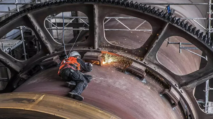
What Is a Girth Gear and Pinion Drive System?
The girth gear and pinion drive is the most widely used transmission method for large rotary kilns. It is commonly found in cement plants, lime production facilities, metallurgical kilns, and hazardous waste incineration systems where high torque and long-term reliability are essential.
The basic principle is straightforward. An electric motor generates rotational power at a relatively high speed. Because a rotary kiln normally rotates at only 0.5 to 4 revolutions per minute, the motor speed must be reduced significantly while increasing output torque. This task is performed by a heavy-duty gearbox.
After speed reduction, the gearbox drives a pinion gear. The pinion meshes with a large girth gear mounted around the kiln shell. As the pinion rotates, the girth gear turns the entire kiln shell, allowing the material inside the kiln to move gradually through the thermal process.
Because power is transmitted through positive gear engagement rather than friction, this system can deliver extremely high torque while maintaining excellent transmission efficiency.
Main Components of a Rotary Kiln Gear Drive System
环齿轮
The girth gear is the largest transmission component in the entire drive assembly. It is mounted around the outer circumference of the kiln shell and serves as the driven element of the gear system.
Depending on kiln size, the girth gear may be manufactured as a one-piece structure or as a split design consisting of two or more segments.
For smaller kilns, a one-piece girth gear provides excellent rigidity and concentricity. However, for large cement kilns with diameters exceeding several meters, split girth gears are generally preferred because transportation and installation become much easier.
Since the girth gear continuously transmits enormous loads, material quality, heat treatment, machining accuracy, and installation precision all play a critical role in determining service life.
Pinion Gear
The pinion is the driving gear that transfers torque from the gearbox to the girth gear.
Although physically much smaller than the girth gear, the pinion is subjected to extremely high contact stresses during operation. As a result, pinions are typically manufactured from high-strength alloy steel and undergo precision heat treatment processes to improve wear resistance.
Helical pinions are commonly used in modern rotary kilns because they provide smoother meshing, lower noise levels, and higher load carrying capacity than straight-tooth designs.
When properly aligned and lubricated, a pinion gear can operate reliably for many years under continuous heavy-duty conditions.
Riding Ring and Support Rollers
The riding ring, sometimes called a tyre, supports the entire kiln shell and transfers its weight onto the support rollers.
Together, the riding ring and support rollers carry hundreds of tons of rotating mass while maintaining proper kiln alignment.
Because the kiln shell expands and contracts as temperatures change, the riding ring must accommodate thermal movement without introducing excessive stress into the structure.
Poor alignment between riding rings and support rollers often results in uneven load distribution, accelerated wear, and increased power consumption.
Thrust Roller
As the kiln rotates, the shell naturally tends to move in the axial direction due to its slight inclination.
The thrust roller is designed to control this axial movement and prevent excessive displacement.
In modern kiln systems, hydraulic thrust rollers are often employed because they can actively adjust kiln position and maintain optimal operating conditions.
Compared with passive systems, hydraulic thrust rollers provide more precise control and reduce mechanical stress throughout the support system.
Gearbox, Motor, and Coupling
The motor, gearbox, and coupling form the power generation section of the transmission system.
The electric motor provides the initial driving force. The gearbox reduces rotational speed while multiplying torque. The coupling connects these components and compensates for minor alignment deviations.
Modern rotary kiln installations increasingly use variable frequency drive (VFD) motors, allowing operators to adjust kiln speed according to process requirements while reducing energy consumption.
Installation Considerations for Girth Gear Drives
Even the highest quality girth gear can fail prematurely if installation procedures are not properly executed.
One of the most important requirements during installation is maintaining correct alignment between the girth gear and pinion. If the gear centerlines are not properly aligned, tooth contact becomes uneven and concentrated on a small portion of the gear surface.
This localized loading dramatically increases wear rates and may eventually lead to tooth cracking or gear failure.
After installation, engineers typically perform tooth contact pattern inspections. A proper contact pattern indicates that the load is distributed evenly across the tooth surface. If abnormal contact marks are detected, adjustments should be made before commissioning.
Another critical step involves tightening all gear connection bolts according to specified torque values. Insufficient bolt preload can cause movement between gear segments, while excessive tightening may introduce unwanted stresses into the structure.
Common Failures and Maintenance Tips
Excessive Tooth Surface Wear
One of the most frequently encountered problems in rotary kiln gear systems is excessive tooth wear.
In many cases, the root cause is not poor gear quality but inadequate lubrication management. When lubrication coverage becomes uneven, direct metal-to-metal contact occurs between meshing teeth, gradually removing material from the tooth surface.
Routine inspection of lubrication systems and periodic measurement of tooth profiles can significantly extend gear life.
Tooth Root Cracking
Tooth root fractures are generally associated with cyclic fatigue loading.
This problem often develops when gears experience repeated shock loads caused by kiln instability, material blockages, or misalignment.
Early detection through non-destructive testing methods can help prevent catastrophic failures.
Abnormal Gear Noise
A sudden increase in gear noise often indicates a developing problem.
Possible causes include improper backlash, tooth damage, insufficient lubrication, or alignment deviations.
Operators should investigate abnormal sounds immediately rather than waiting for visible damage to occur.
Pinion Bearing Overheating
Pinion bearings operate under high loads and require effective lubrication and cooling.
When bearing temperatures begin rising abnormally, engineers should inspect lubrication systems, verify bearing clearances, and check shaft alignment.
Ignoring bearing overheating frequently results in unexpected shutdowns.
Advantages of Girth Gear and Pinion Drives
The popularity of girth gear drives is largely due to their exceptional ability to transmit large amounts of torque efficiently.
For large cement kilns, a single drive unit can generate more than 1,000 kN·m of torque while maintaining transmission efficiency above 90 percent.
In addition, the rigid mechanical connection between the pinion and girth gear provides stable operation under continuous heavy loads. This makes the system particularly suitable for industrial processes where downtime is extremely costly.
Although the initial investment is higher than some alternative drive systems, the long service life and proven reliability often make girth gear drives the most economical solution over the equipment lifecycle.
2. Friction Drive System
Unlike gear-driven systems, friction drives transmit power through direct contact between a driving roller and the kiln shell.
When the drive roller rotates, friction forces generated at the contact surface cause the kiln shell to rotate as well.
One of the biggest advantages of a friction drive system is its simplicity. Because there are no large gears, pinions, or complex gearboxes, installation and maintenance requirements are generally lower.
Another important benefit is the ability to absorb shock loads. Small amounts of elastic slip can help reduce the impact of sudden load fluctuations, protecting mechanical components from excessive stress.
However, friction drives have limitations. As kiln size and weight increase, the amount of torque that can be transmitted through friction becomes restricted. Under wet or contaminated conditions, slippage may also occur.
For these reasons, friction drives are most commonly used in laboratory kilns, small lime kilns, biomass processing systems, and medium-capacity hazardous waste incinerators.
3. Hydraulic Drive System

Hydraulic drive systems use hydraulic pumps and hydraulic motors to generate rotational motion.
Instead of relying on fixed mechanical transmission ratios, hydraulic systems can achieve precise speed regulation by controlling fluid flow and pressure.
This makes hydraulic drives particularly attractive for processes requiring accurate speed control.
In many modern hazardous waste incineration projects, operators need to adjust kiln speed continuously according to feed characteristics, combustion conditions, and residence time requirements. Hydraulic drives provide the flexibility needed to optimize these process parameters.
Another advantage is smooth startup performance. Hydraulic motors can generate high starting torque without introducing significant mechanical shock into the drive train.
The primary disadvantage is system complexity. Hydraulic pumps, valves, pipelines, filters, and fluid management systems all require regular maintenance. As a result, operating costs are generally higher than those associated with traditional gear-driven systems.
4. Chain Sprocket Transmission

Chain sprocket drives transmit power through the engagement of chain links with sprocket teeth.
Compared with friction drives, chain systems provide positive mechanical engagement and eliminate the risk of slippage.
The simplicity and affordability of chain drives make them attractive for smaller thermal processing equipment where investment budgets are limited.
However, chains naturally elongate as wear occurs. Over time, this elongation affects transmission accuracy and increases maintenance requirements.
For large rotary kilns operating under heavy loads, chain drives are rarely selected. Nevertheless, they remain a practical solution for pilot plants, small rotary dryers, and lightweight processing equipment.
Comparison of Rotary Kiln Drive Types
When comparing different rotary kiln drive systems, there is no universally superior solution.
Girth gear drives offer the highest torque capacity and are generally preferred for large industrial kilns operating continuously.
Friction drives provide a simple and economical alternative for smaller installations where torque requirements are relatively low.
Hydraulic drives excel in applications requiring precise speed control and process flexibility.
Chain sprocket systems remain a cost-effective option for light-duty equipment and pilot-scale projects.
The final selection should consider kiln diameter, operating temperature, production capacity, maintenance capabilities, and total lifecycle costs rather than focusing solely on initial investment.
结论
The drive system determines how efficiently and reliably a rotary kiln can perform throughout its service life. While girth gear and pinion drives continue to dominate large-scale cement, lime, metallurgical, and waste treatment projects, friction, hydraulic, and chain-driven systems each offer advantages under specific operating conditions.
Understanding the working principles, strengths, and maintenance requirements of each drive type allows engineers and plant operators to make informed decisions that improve productivity, reduce downtime, and maximize return on investment.
As rotary kiln technology continues to evolve, selecting the right transmission solution remains one of the most important factors influencing long-term equipment performance.


 Chinese
  English
  Russian
  Arabic
  Vietnamese
  Spanish
  French
  Portuguese
  Japanese