


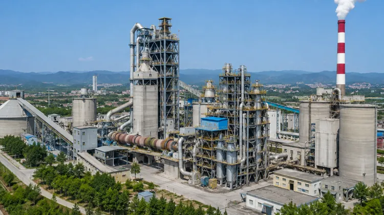
Carbon dioxide emissions from cement production come from both fuel combustion and the chemical decomposition of limestone during clinker production.
Even if a cement kiln were powered entirely by low-carbon energy, limestone calcination would continue to release process CO₂. Carbon capture, utilization, and storage is therefore an important solution for addressing residual emissions after clinker reduction, alternative fuels, and energy-efficiency measures have been applied.
The GCCA identifies CCUS as a major part of the cement and concrete sector’s net-zero pathway because a substantial share of cement emissions results directly from raw material chemistry.
What Is Carbon Capture in the Cement Industry?
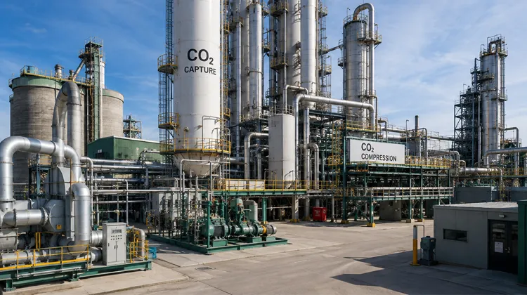
Carbon capture in the cement industry means separating CO₂ from kiln or calciner exhaust gas before purifying and compressing it for utilization or permanent storage.
The terminology depends on the final destination of the captured gas:
Carbon capture and storage, or CCS, transports captured CO₂ to a suitable geological formation for long-term storage.
Carbon capture and utilization, or CCU, uses CO₂ as a feedstock for mineralized construction materials, chemicals, synthetic fuels, or other industrial products.
Carbon capture, utilization, and storage, or CCUS, is the broader term covering both pathways.
Not every CO₂ utilization route provides permanent storage. Carbon used in some fuels or chemicals may eventually return to the atmosphere, while mineralization can convert it into stable carbonate materials. The U.S. Department of Energy identifies mineralization as a pathway for producing synthetic aggregates, carbonate materials, and other construction products.
Why Is Carbon Capture Important for Cement Plants?

Portland cement clinker is produced by heating limestone, clay, and corrective materials at high temperatures.
During calcination, calcium carbonate decomposes into calcium oxide and carbon dioxide. These process emissions are independent of the fuel used to heat the kiln.
Direct-separation technology sources estimate that limestone calcination accounts for approximately two-thirds of cement manufacturing CO₂. Because this part of the emissions cannot be eliminated through conventional fuel switching or energy-efficiency improvements, carbon capture is an important option for producing near-zero-emission cement.
How Does Carbon Capture Work in a Cement Plant?

The exact arrangement depends on the capture technology, but a complete cement plant CCS system normally includes several main stages.
Flue Gas Collection
CO₂ is commonly captured from exhaust gas leaving the kiln, preheater, or calciner system.
The gas may also contain dust, water vapor, nitrogen oxides, sulfur oxides, oxygen, and other components. Gas temperature, flow rate, CO₂ concentration, and impurity levels influence the size and performance of the capture plant.
Flue Gas Pretreatment
Most capture technologies require relatively clean and stable flue gas.
Bag filters or electrostatic precipitators remove dust, while additional desulfurization, denitrification, and gas cooling may be required. Amine solvents can be particularly sensitive to impurities, which may accelerate solvent degradation and increase chemical consumption.
CO₂ Separation
The pretreated flue gas enters an absorber, membrane unit, calcium-looping system, or another separation process.
CO₂ is separated from nitrogen, water vapor, oxygen, and other gas components. The separation method determines much of the system’s heat demand, electricity consumption, equipment arrangement, and operating cost.
Purification and Dehydration
The captured gas may still contain moisture, oxygen, and trace impurities.
It must be purified and dried to meet pipeline, ship transport, storage, or downstream utilization specifications. Excess moisture can cause pipeline corrosion or hydrate formation under certain pressure conditions.
Compression or Liquefaction
Pipeline transport generally requires multi-stage CO₂ compression.
Ship transport may require cooling and liquefaction. Compressors, intercoolers, dehydration units, separators, heat exchangers, storage tanks, and loading systems are therefore important parts of the carbon-management chain.
Transport, Utilization, or Storage
Conditioned CO₂ can be transported by pipeline, ship, or tanker to a utilization facility or geological storage site.
For permanent storage, it may be injected into deep saline formations, depleted oil and gas reservoirs, or other carefully evaluated geological structures. Long-term monitoring is required to verify storage integrity.
Main Carbon Capture Technologies for Cement Plants
Amine-Based Post-Combustion Capture
Amine-based post-combustion capture is one of the most mature options available to the cement industry.
Kiln exhaust gas enters an absorber and contacts an amine solvent. The solvent selectively absorbs CO₂, while most other gases leave the top of the tower.
The CO₂-rich solvent is then heated in a regeneration column. Concentrated CO₂ is released, and the regenerated solvent returns to the absorber.
A major advantage is that the system can be installed downstream of an existing cement kiln without completely redesigning the clinker-burning process.
The main disadvantages are the heat required for solvent regeneration and the need for effective dust, SOx, and NOx control. Solvent degradation, corrosion, waste handling, and chemical replacement must also be considered.
GCCA describes amine-based post-combustion capture as the most advanced carbon capture option currently available to cement producers.
Oxyfuel Combustion
Conventional kilns use air for combustion, and the nitrogen in air dilutes the CO₂ concentration in the exhaust gas.
Oxyfuel combustion replaces air with oxygen-rich gas. This produces exhaust with a much higher CO₂ concentration, making purification and storage preparation easier.
Full oxyfuel can cover the complete pyroprocessing system, while partial oxyfuel may focus on the raw material calcination stage. Full oxyfuel can offer higher capture potential but requires more extensive modifications to the preheater, calciner, burner, cooler, and gas circulation system.
A typical oxyfuel installation requires:
- An air separation unit;
- Oxygen compression and distribution;
- Flue gas recirculation;
- Modified burners and cooling equipment;
- Improved process sealing;
- CO₂ purification and compression.
Producing oxygen requires considerable electrical power, making low-carbon electricity supply an important part of project economics.
Calcium Looping
Calcium looping uses calcium oxide to capture CO₂ from cement plant exhaust.
Inside the carbonator, CaO reacts with CO₂ to form calcium carbonate. The carbonate is then transferred to a calciner operating at approximately 850°C to 950°C, where it releases a concentrated stream of CO₂ and regenerates CaO for reuse.
The process has potential compatibility with cement production because cement plants already handle calcium-rich materials. Spent sorbent may also be incorporated into cement raw materials.
The main challenges are the heat required for sorbent regeneration, gradual loss of sorbent activity, and the complexity of integrating additional reactors into an operating cement plant.
Direct Separation and Indirect Calcination
Direct separation changes the way limestone is heated.
In a conventional calciner, combustion gases mix with the CO₂ released from limestone. In an indirect calcination system, heat is transferred through a reactor wall, keeping the process CO₂ separate from combustion exhaust.
Because the resulting gas mainly contains CO₂ and steam, water can be condensed to produce a relatively concentrated CO₂ stream without a large chemical absorption unit.
Direct separation mainly captures process emissions. Additional measures are required if fuel-related emissions must also be captured.
The technology still needs further commercial-scale integration with standard cement kiln systems, but it offers a potentially energy-efficient route for unavoidable calcination emissions.
Membrane Separation and Solid Sorbents
Membrane separation uses selective materials that allow CO₂ to pass more readily than other flue gas components.
Membrane systems can be compact and avoid large quantities of liquid solvents. However, multiple membrane stages, compression, or vacuum equipment may be necessary to achieve both high recovery and suitable CO₂ purity.
Solid sorbents capture CO₂ on porous materials and release it through changes in temperature or pressure. They may reduce corrosion and liquid waste, but sorbent life, regeneration energy, and performance under large cement kiln gas volumes remain important development areas.
GCCA includes membranes, solid sorbents, and chemical absorption among the main post-combustion capture approaches under development.
Comparison of Cement Carbon Capture Technologies
| Technology | Main Advantages | Main Challenges | Applications appropriées |
|---|---|---|---|
| Amine post-combustion capture | Commercially advanced and suitable for retrofits | High regeneration heat and sensitivity to impurities | Existing cement plants |
| Oxyfuel combustion | Produces high-concentration CO₂ and offers high capture potential | High electricity demand and major kiln modifications | New or deeply upgraded clinker lines |
| Calcium looping | Compatible with calcium-based cement materials | Complex reactors, heat demand, and sorbent degradation | Plants with strong heat-integration opportunities |
| Direct separation | Produces concentrated process CO₂ without large solvent systems | Commercial scale-up and kiln integration are still developing | New calciner and process designs |
| Membranes and solid sorbents | Compact and potentially modular | Purity, recovery rate, and material life require optimization | Modular or hybrid capture systems |
Equipment Required for Cement Plant Carbon Capture
A cement carbon capture project involves much more than adding an absorption tower.
Flue Gas Treatment Equipment
The front end may include bag filters, electrostatic precipitators, desulfurization equipment, NOx-control systems, gas coolers, ducts, dampers, and induced-draft fans.
This equipment prepares the exhaust gas for stable capture operation.
Absorption and Regeneration Equipment
An amine system normally includes an absorber, regeneration column, reboiler, heat exchangers, solvent pumps, filtration equipment, and solvent storage tanks.
Equipment size depends on flue gas flow, CO₂ concentration, target capture rate, and solvent performance.
Heat Supply and Waste Heat Recovery
Amine regeneration, calcium looping, and several other capture processes require substantial heat.
Available waste heat from the kiln exhaust, clinker cooler, or waste heat recovery system can reduce the demand for additional fuel. The Brevik capture project also uses heat recovered from cement manufacturing to improve the capture process.
CO₂ Purification and Compression Equipment
Captured CO₂ normally passes through dehydration, purification, and multi-stage compression.
The system may include compressors, intercoolers, separators, dryers, analyzers, and high-pressure piping. Ship transport may also require liquefaction equipment, low-temperature storage tanks, and loading facilities.
Automation and Safety Systems
The capture plant must operate in coordination with the kiln, process fans, heat recovery, power supply, and CO₂ export system.
Because high CO₂ concentrations can create an asphyxiation hazard, compressors, enclosed rooms, and storage areas require gas detection, ventilation, pressure protection, and emergency shutdown systems.
Key Considerations When Retrofitting a Cement Plant
Flue Gas Conditions
Flow rate, CO₂ concentration, oxygen, moisture, dust, SOx, and NOx must be measured over representative operating periods.
Kiln condition, fuel type, and raw material variation can all change gas composition, so the design should not rely on a single measurement.
Energy Supply
Carbon capture increases steam, electricity, cooling, and auxiliary power demand.
The plant should evaluate grid capacity, low-carbon electricity, available waste heat, and the possible need for additional boilers or power-generation equipment.
Space and Plant Layout
Absorbers, regeneration columns, compressors, tanks, and large gas ducts require considerable space.
Older cement plants may have restricted layouts, complex underground services, and limited shutdown periods. Three-dimensional scanning and construction-sequence planning are therefore important during front-end engineering.
CO₂ Transport and Storage
Capture is only the first part of a CCS value chain.
A plant also needs reliable access to a pipeline, port, shipping system, utilization customer, or permitted geological storage site. Transport and storage planning should therefore begin before the capture unit is finalized.
Capital and Operating Costs
Carbon capture adds equipment investment, energy use, maintenance, staffing, and chemical costs.
The IEA estimates that production costs at early commercial near-zero-emission cement plants using CCS may be approximately 75% to 150% higher than those at conventional plants, depending on regional conditions.
Commercial projects may therefore depend on carbon pricing, public procurement, government support, low-carbon cement premiums, or long-term transport and storage contracts.
Combining Carbon Capture with Other Cement Decarbonization Measures

Carbon capture should not replace clinker reduction, energy efficiency, or alternative fuels.
A more efficient strategy is to reduce emissions first through supplementary cementitious materials, efficient kilns, optimized grinding, waste-derived fuels, and low-carbon electricity. Capture technology can then address the remaining emissions.
Reducing the amount of CO₂ entering the capture plant can lower the required size of absorbers, compressors, pipelines, and storage facilities.
Several cement decarbonization projects supported by the U.S. Department of Energy combine calcined clay, alternative fuels, and carbon capture within the same overall strategy.
Cement Industry Carbon Capture Projects
Brevik CCS
The Brevik CCS facility in Norway was officially inaugurated in June 2025 as the first industrial-scale CCS facility in the cement industry.
It is designed to capture approximately 400,000 tonnes of CO₂ annually, representing around 50% of the plant’s emissions. Captured CO₂ is liquefied, transported by ship, and then sent by pipeline for permanent storage beneath the North Sea.
The project demonstrates how capture, liquefaction, shipping, and geological storage can be connected to an operating cement plant.
Mitchell Cement Plant Project
The U.S. Department of Energy-supported Mitchell project plans to construct an integrated carbon capture, transport, and geological storage system.
According to the project plan, the system aims to capture at least 95% of the relevant CO₂ and prevent approximately two million tonnes per year from entering the atmosphere. As the project is still under development, its final performance should be evaluated using future operating data.
Challenges Facing Carbon Capture in the Cement Industry
Carbon capture is moving from pilot testing toward industrial deployment, but several obstacles remain.
Capture, regeneration, purification, and compression increase energy demand. Plants without access to low-carbon power or usable waste heat may require additional energy infrastructure.
Many cement plants are also located far from suitable geological storage sites. Long-distance pipelines or shipping systems add cost and require coordination among producers, infrastructure operators, regulators, and local communities.
The capture system must operate alongside a continuously running cement kiln. Variations in kiln exhaust or interruptions in either the cement plant or capture unit can reduce overall performance.
Although planned near-zero-emission cement capacity for 2030 is increasing, the IEA reports that the current project pipeline remains below the deployment rate required by its net-zero scenario.
Future of Carbon Capture in Cement Manufacturing
No single carbon capture technology will be suitable for every cement plant.
Existing production lines may favor amine-based or other post-combustion systems. New clinker plants may integrate oxyfuel, direct separation, or calcium looping from the design stage. Smaller or space-constrained plants may eventually use modular membrane or solid-sorbent systems.
Shared CO₂ pipelines, ports, shipping networks, and regional storage hubs can allow several cement and industrial plants to use common infrastructure, reducing the burden on individual projects.
Future cement plants will increasingly be designed not only around the movement of raw meal, clinker, and fuel, but also around heat integration, CO₂ conditioning, transport, and storage.
Conclusion
Carbon capture is an important option for addressing unavoidable process emissions from limestone calcination.
A complete cement CCUS project must integrate flue gas pretreatment, CO₂ separation, heat supply, purification, compression, transport, and storage.
Amine post-combustion capture is currently one of the most practical retrofit technologies. Oxyfuel and direct separation may be better suited to deeper process redesign, while calcium looping offers potential integration with calcium-rich cement materials.
Technology selection should be based on representative flue gas data, energy balance, equipment layout, CO₂ transport options, and access to reliable utilization or geological storage.
FAQ
Where does CO₂ come from in a cement plant?
It comes mainly from limestone calcination and from the fuel used in the rotary kiln and calciner.
How much CO₂ can a cement plant capture?
The potential capture rate depends on the selected technology and system boundary. High capture rates are technically possible, but actual performance depends on flue gas conditions, plant availability, energy supply, and equipment operation.
Which capture technology is best for an existing cement plant?
Amine-based post-combustion capture is often considered suitable for retrofit because it can be installed downstream of the existing kiln gas system. However, it still requires gas cleaning, heat supply, compression, and CO₂ export equipment.
Does carbon capture affect cement quality?
Post-combustion capture normally does not directly change clinker chemistry. Oxyfuel, calcium looping, and direct separation interact more closely with clinker production and therefore require careful validation of kiln operation and product quality.
What happens to the captured CO₂?
It can be used in mineralized building materials, chemicals, or other industrial processes, or transported to a geological storage site for long-term containment.
Can carbon capture eliminate all cement plant emissions?
Not completely in every case. Capture equipment consumes energy and may leave residual emissions. It should therefore be combined with clinker reduction, efficient equipment, alternative fuels, and low-carbon electricity.


 French
  English
  Russian
  Arabic
  Vietnamese
  Spanish
  Portuguese
  Japanese
  Chinese